Сalculation table
Fuel Level Sensor (FLS)
Before configuring the calculation table for the fuel level sensor (FLS), perform a fuel tank calibration to obtain a table where X values correspond to the sensor readings and Y values represent the fuel volumes.
|
Входное значение X |
Выходное значение Y |
|---|---|
|
1 |
0 |
|
110 |
30 |
|
365 |
60 |
|
525 |
90 |
|
688 |
120 |
|
874 |
150 |
|
1060 |
180 |
|
1415 |
240 |
|
1770 |
300 |
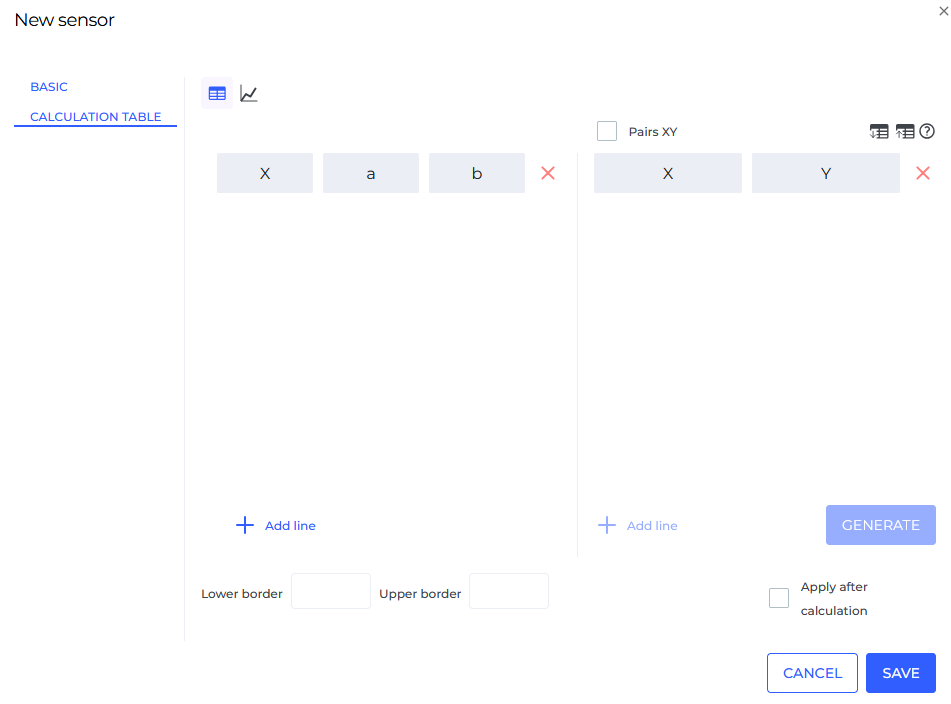
After creating the fuel level sensor, go to the Calculation Table menu.
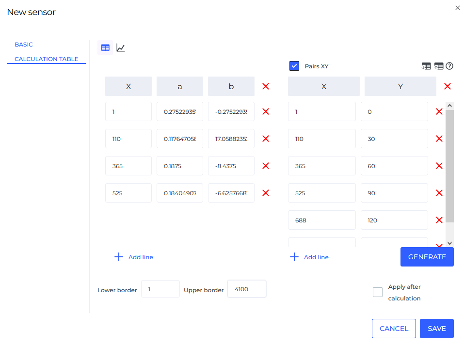
- Enable XY pairs and add the required number of rows according to the data obtained from the fuel tank calibration.
2. Carefully enter your readings into the table, set the lower and upper bounds according to your device's specifications, and click the Generate button.
3. For a visual understanding of how the fuel level sensor (FLS) is configured, you can open the calculation graph by clicking on the Graph button.  :
:
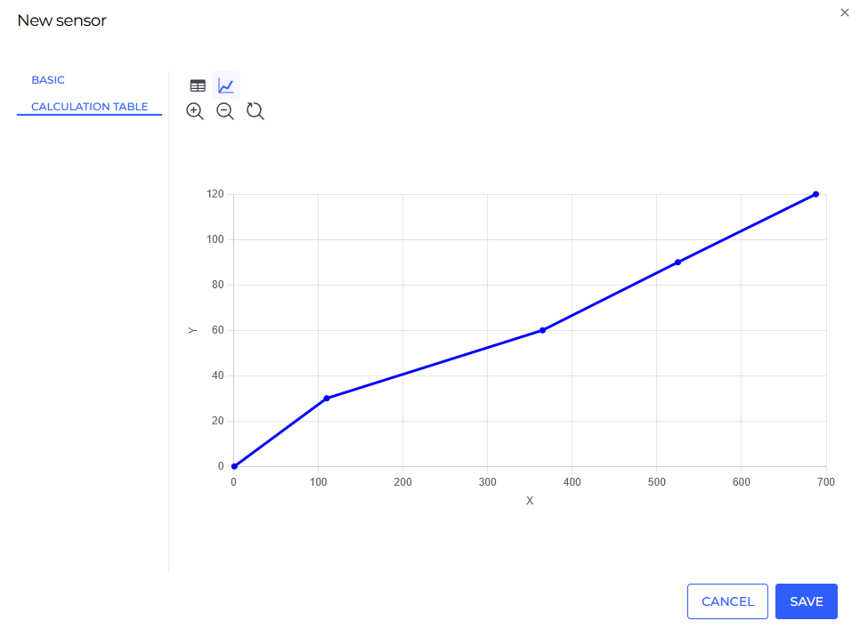
4. Click Save.
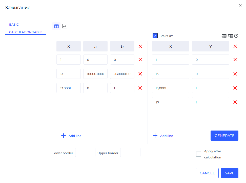
Ignition Sensor
Let’s look at an example of how to fill out the calculation table for an analog ignition sensor, which operates based on voltage measurement. In this case, the ignition status is determined by the signal voltage level: if the voltage does not exceed 13 V, the ignition is considered off; if the voltage is above 13 V, the ignition is considered on.
Once the ignition sensor has been created, go to the "Calculation Table" section and specify the appropriate column pairs on the right side of the table, based on the voltage values typical for your vehicle, then click the generate button.
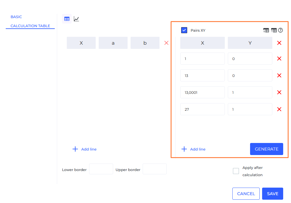
After the values are generated, the system will be able to determine at what voltage level your vehicle turns the ignition on or off.