Fuel Level Sensor (FLS)
Fuel Level Sensor (FLS) in a Monitoring System
A Fuel Level Sensor (FLS) is a device designed to measure the current volume of fuel in a vehicle’s tank. In monitoring systems such as Wialon or Wiafleet, the FLS is a critical component that ensures accurate fuel consumption tracking, helps prevent theft, and enables analysis of vehicle efficiency.
How It Works
The FLS is installed in the fuel tank and measures the fuel level, converting it into an electrical signal (voltage, current, or frequency). This signal is transmitted to a GPS tracker, which then sends the data to the monitoring system server. The data is processed and displayed as:
-
Current fuel level
-
Fuel consumption graphs
-
Events (refueling, fuel drain)
-
Fuel efficiency reports
Configuration in the Monitoring System
Once the FLS is installed and connected:
-
Create the sensor in the system (set the type: “Fuel Level Sensor”).
-
Input or upload the calibration table.
-
Set measurement units (typically liters).
-
Specify additional FLS parameters as required (such as filtering, offset, sensor input type, etc.).
Benefits of Using an FLS
-
Accurate tracking of refueling and fuel drains
-
Prevention of fuel theft
-
Analysis of fuel efficiency
-
Reduced operating costs
-
Greater transparency in driver and vehicle performance
Configuring Fuel Level Sensors (FLS) for Dual-Tank Vehicles:
For vehicles with two fuel tanks, it is common to install one fuel level sensor (FLS) in each tank. To obtain accurate data on total fuel volume and consumption, it is necessary to combine the readings from both sensors within the monitoring system.
-
Creating Two Custom Sensors
A separate sensor should be created for each tank:
-
Type: Custom sensor
-
Names: For example,
DUT1andDUT2
2. Setting the Parameter
-
In each sensor, specify the parameter that corresponds to the input data from the respective FLS.
For example:
-
fuel2— for the left tank -
fuel3— for the right tank
These parameters should match the ones sent by the GPS tracker or telematics unit.
-
3. Adding Calibration Tables
-
Each sensor must have its own calibration (scaling) table, which defines the relationship between the fuel level and the actual fuel volume.
-
Calibration must be performed individually for each tank, as their shapes and volumes may differ.
-

2. Creating a Calculated Sensor for Total Fuel.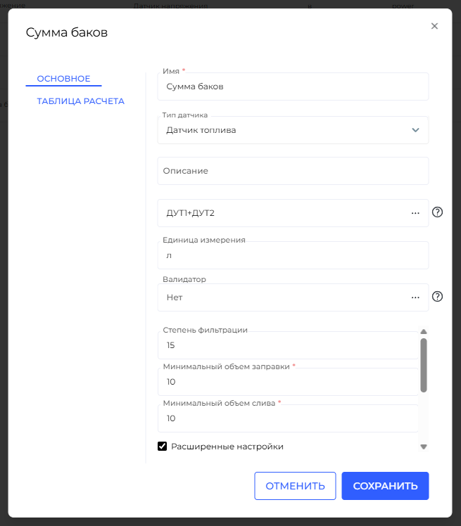
To display the total fuel volume from both tanks, you can create a calculated sensor that sums the values of DUT1 and DUT2.е параметров в формуле
-
-
You can directly use the names of the previously created sensors (e.g.,
DUT1andDUT2) in the formula. -
There is no need to specify
const, enclose values in parentheses, or perform complex referencing — Wiafleet automatically substitutes the current values from the named sensors.
⚠️ Note: In this case,
DUT1andDUT2refer to the names of custom sensors, not raw hardware parameters. -
Naming Recommendations
-
To ensure proper operation of formulas and avoid system errors:
-
Avoid spaces, special characters, or punctuation in sensor names.
-
Use simple, clear names:
DUT1,DUT2,FuelTotal,Fuel_LeftTank.
-